
Troubleshooting flash is complicated, and often there is a lot of tail-chasing on the shop floor in trying to get a solution. This approach should lead you to the solution via a data-driven procedure.
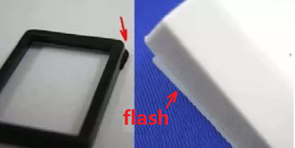
Testing the parting line, using pressure-indicating paper: The image on the left is flash-free. The part on the right side is flashed; note the location of flash where the paper is mostly white at the top and bottom. The white color indicates the parting-line touch force is below 1500 psi. The paper does not start to turn pink until there is at least 1400 psi of touch force. So when I raised the hold pressure to really pack out the part, it flashed at the top and bottom. (You do not see the flash on top due to the angle of the shot.)
Flash has to be one of the top 10 problems molders face, causing rejects and a significant dent in profits. Troubleshooting flash is complicated, and often there is a lot of tail-chasing on the shop floor in trying to get a solution. Here is a strategy that should lead you to the solution via a data-driven procedure.
Flash can appear on the part’s edge along the parting line of the mold, or anyplace where the mold has metal meeting metal to form a boundary of the part. Flash can occur for several reasons, including variations in the process, mold issues, machine problems, or material issues.
First, I’ll assume: 1) You have checked the parting line carefully and that it is clear of any foreign material; and all slides, etc. are clean and clear of flash or buildup of residue. 2) You are running the process under velocity control and not pressure-limited.
To start, find out if the flash is occurring in the first or second injection stage. Here’s how: Take off second-stage or pack and hold pressure by reducing the pressure to a very low level—shoot for no more than 500 psi plastic pressure. It is important that you do not take off the second-stage or hold time. Check out the part after injection under these conditions: It should be visibly short at the fill time you established and at the normal transfer pressure. If it isn’t, readjust the cut-off position to make the part short.
Once you’ve made a short shot, look for flash. If the part is flashed you have evidence that the parting line is most likely the problem and needs repair. It is difficult, if not impossible, to process around a weak parting line. If you’re running a multi-cavity tool, make a short shot where all parts are short. Be careful—with some tools, shorts may not eject. Use mold release if necessary. If the short shot shows that cavity filling is non-uniform, this means packing cannot be uniform. This is why parts from multi-cavity molds may experience flash in one cavity and sink marks in another on the same shot. A previous column (t)see Editor’s Picks top right) discusses this problem.
Is the parting line is OK? To check this, don’t use bluing compound. Instead use a special pressure-sensitive paper that develops a red color relative to the amount of pressure developed. The parting line may be perfect on a bench press but not tight when clamped by the molding press. Clamping in most machines exhibits something known as platen wrap. The platens literally bow around the mold. The photo shows how bowing manifests itself in the part.
The picture on the left is flash-free, the parting line is mating all the way around and the vents are open. The indicator paper tells us the side parting lines provide a touch force of 5000 to 6500 psi, as indicated by the deep red color. The part on the right side is flashed where the indicator paper is mostly white at the top and bottom. The white color indicates the parting-line touch force is below 1500 psi. The paper does not start to turn pink until there is at least 1400 psi of touch force.
So when I raised the hold pressure to really pack out the part, it flashed at the top and bottom. The mold works perfectly on the bench, but when clamped in a machine it cups 0.001–0.003 in., and it needs preloaded support pillars at the top and bottom to prevent the development of flash at higher second-stage or hold pressures.
Clamp misalignment can also cause flash. Check machine leveling and clamp parallelism, which can also produce flash.
If you get no flash on the shorts from first-stage injection only, you have established that flash is occurring in the second stage. It still may be a parting-line issue, as shown in the photo, but the indicator paper provided the data to answer that question. We have reduced the complexity of finding the root cause—it has to be something related to hold pressure. There are only a couple of exceptions to this conclusion: thin-wall molding, where cavity pressures can be very high in filling to cause flash; and micro-molding, where parts are so small that you cannot separate fill from pack (i.e., there are no first and second stages).
Going back to the point where you have shorts and no flash, now start adding hold pressure, starting low, with about 500 psi plastic pressure in the nozzle. As you raise the second-stage pressure, watch for when and where flash shows up. If flash develops with low pack and hold pressures, this again suggests the culprit is the parting line, clamp, or press leveling.
If the flash is in the center of the mold, it may be due to inadequate mold support. Molders should consider whether the mold has enough support pillars in the right places for the cavity and core plates. Molds deform upon clamping, and to combat this they are often built “preloaded” so that the center support pillars are slightly taller than others.
The sprue bushing is another possible source of flashing. Nozzle contact forces can range from 5 to 15 tons. If thermal expansion causes the bushing to “grow” far enough past the parting line, the nozzle contact force can be enough to push on the moving side of the mold, trying to open it. For non-sprue-gated parts, molders should check the length of the sprue bushing while it is hot.
Next, let’s examine clamping. If the flash is concentrated toward the center of the mold, it could be caused by too-high clamp pressure. If a small mold is mounted on a large platen, the forces on the mold can be greater on the four outside corners than in the center. The excessive clamp pressure may tend to “wrap” the platens around the mold. To solve the problem, be sure that the mold takes up about 70% of the distance between the tiebars.
Flash can also be caused by too little clamp tonnage. If the part passes the first-stage short-shot test without flash, then the pack/hold phase may be pushing the parting line apart. Increasing the clamp tonnage may be the solution. That’s especially true of high-speed filling in a thin-wall application, which can require 35,000 to 60,000 psi plastic pressure in the nozzle.
If material viscosity is too low, flashing can result. Resin can become too “runny” for a variety of reasons: melt temperature too high, excessive residence time that causes degradation, too much moisture in moisture-sensitive resins like nylon, or excessive amount of colorant or other additive that contains a lubricating vehicle. You can take the temperature of the melt at the nozzle with an infrared detector.
Tags: Injection Molding, Plastic Parts